
Residential high-pressure water mist
iCO two-pump
system guide
For new residential iCO high-pressure projects, TM Services specifies two pump units with the MK2 concealed nozzle. Both units feed one network serving the protected rooms.
Read the installation guide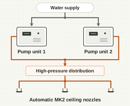
System operation
From the supply to the room
Water enters both pump units
Each unit takes water from the agreed supply and feeds the common high-pressure line. The two cabinets shown in the diagram are complete pump units. The design must establish the duty each unit provides, the water available while the pumps run and how long that supply will last. The residential schematic shows isolation, a strainer, a pressure gauge and a drain at the units so the installer can inspect, test and service the equipment.
Heat opens the nozzle nearest the fire
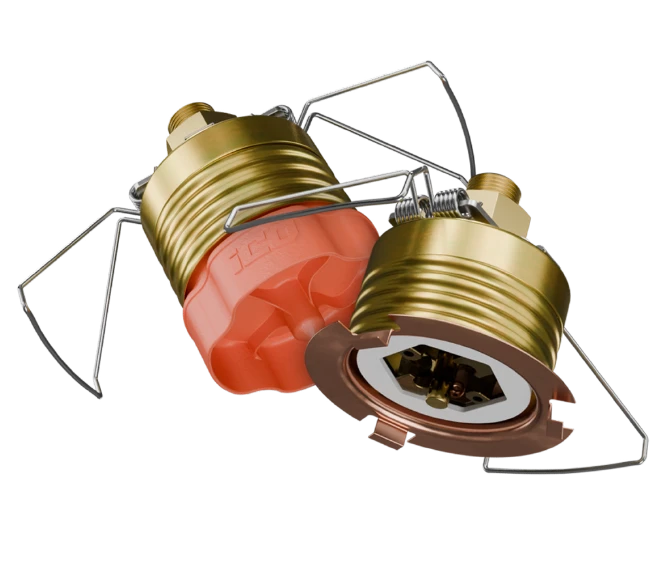
The MK2 cover releases at its rated temperature of 57°C. As heat builds, the nozzle’s 68°C glass bulb releases, opening the waterway. Water discharges through the open nozzle as a fine mist. Other nozzles stay closed until sufficient heat reaches them.
The controls depend on the design
iCO describes wet and pre-action arrangements. In a pre-action system, a signal from the building’s detection system also forms part of the release sequence. The project drawings identify the selected mode and the signals that must pass between the fire alarm and the pump controls.
iCO-HP-09
The MK2 ceiling nozzle
Ceiling coordination
- Ceiling opening
- 60 mm diameter
- Clear void above ceiling
- 130 mm minimum
- Finished cover
- Approx. 6 mm below ceiling
- Flat-ceiling layout
- Up to a 4 m × 4 m grid, at least 2 m between nozzles and up to 2 m from a wall
iCO shows at least 500 mm clearance from a pendant light. Sloping ceilings have separate pitch and apex rules. Send the ceiling plan with lights, beams and changes of level marked so the designer can place each nozzle.
Pressure at the nozzle
iCO publishes two operating conditions for the MK2. These values describe nozzle performance. The engineer calculates the pump duty separately, allowing for elevation and pressure losses along the actual route.
| Open nozzles | Min. pressure | Published flow* |
|---|---|---|
| One | 60 bar | 14.7 L/min |
| Two | 26 bar | 18.9 L/min |
*Flow for the activation condition shown, as listed in iCO’s datasheet. The design must address the number of nozzles required to operate together for the specific occupancy.
Installation guide
What happens on your project
This is a client coordination guide. The installation team works to the project’s issued drawings and iCO’s applicable design, installation, operation and maintenance instructions.
Survey the building and water supply
We review the fire strategy, plans, building use and ceiling heights. A flow test records how much water is available and the pressure while it is flowing. Where the supply also serves taps and appliances, the designer checks competing demand and specifies any priority demand valve on the domestic branch.
Agree the layout and pump duty
The design identifies protected rooms, operating nozzles, network routes and the required run time. Hydraulic calculations check the pressure available at the most demanding nozzles. If the supply or room layout falls outside the supported limits, the design needs resolving before installation.
First fix before ceilings close
Reserve accessible space for both pump units, their dedicated power supplies, isolation, drainage and alarm connections. For the V2 cabinet, iCO gives dimensions of 342 mm wide × 342 mm deep × 495 mm high and calls for 100 mm ventilation clearance on each side. Leave room to remove the front covers for servicing. The installer routes and supports the specified high-pressure lines and records concealed work.
Fit the nozzles and connect the controls
Check the finished ceiling against the coordinated layout before cutting openings. The installer fits each specified MK2 assembly and its cover, checks clearances, and connects the pump controls and any fire alarm interface shown on the drawings. Refer ceiling or lighting changes back to the designer before moving a nozzle.
Commission and hand over
The installation team checks the network for leaks, verifies measured performance against the design, proves the operation of both pump units and tests the required fire and fault signals with the alarm contractor. At handover, ask for the as-built layout, design duty, commissioning results, both pump serial numbers, user instructions and service contacts.
Design evidence
How the standards apply
For a new installation
BS EN 14972-1:2020+A1:2025 covers system design, installation, inspection and maintenance. BS EN 14972-17:2025 defines residential fire tests for automatic nozzle systems. iCO reports MK2 tests A–E at a 2.5 m ceiling and test A at 3.5 m. The higher test height applies to that one test only.
Building use matters. For example, iCO identifies a minimum of four operating nozzles for certain residential occupancies, including residential care premises. The two-nozzle figures above cannot establish the duty for those projects. The V2 drawing illustrates the plumbing arrangement. The MK2 datasheet reports nozzle test results. For the proposed combination, the designer checks the applicable iCO manual and supporting test evidence against the building and confirms that the pumps can deliver the calculated duty.
If you already have a single-pump system
TM Services uses the two-unit arrangement for new high-pressure MK2 specifications covered by this guide. For an existing installation commissioned under BS 8458:2015, its original design, approval, service history and any change of use all matter. Withdrawal of BS 8458 alone does not establish that your system needs replacing.
After handover
Keep the pump area accessible, the nozzle covers clear of paint and obstructions, and the manual and certificates available. iCO calls for annual maintenance by an iCO installer. Contact the installer before changing partitions, ceilings or the use of a protected room.
Technical references
Manufacturer documents
References checked 10 November 2026. For construction, use the issue confirmed for your project.
Planning an installation?
Send your floor plans, ceiling layouts and fire strategy so we can review the two-pump arrangement for your building.